20.109(F11): Mod 3 Day 3 TEM
_homepage.jpg)
TEM
Introduction
The Transmission Electron Microscope (TEM) achieves its remarkable resolution by “illuminating” samples using an electron beam in a vacuum rather than using a conventional light source in air. Since the electron beam passes through the sample that is being examined, the sample must be sufficiently thin and sufficiently sturdy to be hit by electrons in a vacuum. It’s important to remember that many biological materials are damaged or destroyed by the incoming electrons and that the TEM can image only the species that survive this harsh treatment. The denser parts of the sample will absorb or scatter some of the electron beam, and it’s the scattered electrons or those that pass through the sample that are focused using an electromagnetic lens. This “electron shadow” then strikes a fluorescent screen, giving rise to an image that varies in darkness according to the sample's density. For samples that are amenable to TEM, this form of examination can allow observation of angstrom-sized objects and of cellular details down to near atomic levels.
Samples were applied last time to a wafer-thin "grid" and today they will be loaded into the TEM and placed under vacuum. The grid can be made of many kinds of materials. All have lines of a conductive metal, in our case copper, that disperse the electron beam and thereby help keep the sample from being blown to bits by the energy in the beam. A carbon mesh is strung between the metal lines. Once a sample has been applied to the grid, it's only the portions that come to rest on the carbon mesh can be visualized, along with any imperfections in the carbon mesh itself.
Protocols
We're fortunate to have Dr. Dong Soo Yun from Angie Belcher's lab who will run the TEM grids you prepared. We've reserved the 2010FEG TEM, which is located in the basement of Bldg 24. Since the room that houses the instrument is small, we'll head over in our "supergroups," starting at about 1:30. The grids will take less than an hour to visualize and when you're not at the TEM, you should be working with your lab partner on your research proposal.
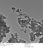
Here are some examples of the kinds of images you'll get at TEM today:


DONE!
For next time
- Prepare a figure of your nanowires from one of the TEM images that has been posted. The figure should be "publication ready," i.e. with all the traditional elements found for figures in a research article. If you'd like to examine other figures from TEM studies, consider some of the Belcher lab's publications, e.g. Nano Lett., 2005, 5 (7), pp 1429–1434 DOI: 10.1021/nl050795d or Nano Lett., 2010, 10, pp 2433-2440 DOI: 10.1021/nl1005993
- You should now be refining your research idea enough to start considering the presentation materials themselves. If you can, start working on the materials you will use to present your idea. Reconsult the specific directions for what you'll need as well as the more general guidelines for all oral presentations.