2020(S10) Lecture:week 7
Week 7 Tuesday
Over the next few weeks we will spend nearly all of our lecture and studio time specifying these aspects of your project:
- a high level system specification (i.e. a plain language overview of what your project will do)
- a pseudo-code description of your system (i.e. a series of IF, THEN statements that program your cell)
- a block diagram showing the system's architecture (i.e. a simple series of squares inside a cell to show functions and their connections)
- a device/modules list
- a timing diagram
- a parts list
Be ready to revise what seemed like completed aspects of your project as you learn more about what's available and how things work. Design/revise/design/revise/design/revise....that's what the next few weeks will be all about...
Project Selection Status?
- Brief report of each team's project selection status.
Challenge: System Overview
Part 1: The big picture
Hold onto your hats. We'll start today with an example of a mature project from Ron's lab that illustrates a system behavior and the complex programming that underlies it. This should motivate the work we'll do this week to move from your project ideas to rationally program the behaviors.
Part 2: Bacterial Buoy
- Next you and your project team will describe the highlevel a system behavior for an engineered system, namely for the Melbourne 2007 iGEM "coliform" project.
- The Melbourne team wanted to build a 3D, floating mass of bacteria that adhered to one another when the cells detected both blue and red light. In other words: at the intersection of an incoming red light beam and blue light beam, a solution of bacteria would clump and remain suspended in its growth media.

- As a class we'll watch the first 5 minutes of the Melbourne team's iGEM presentation.
- Next your project team should work out a high level overview of the system's behavior for the coliform project and some pseudo-code to program this behavior. Finally write on the white board a block diagram that connects the inputs and outputs for the cell. You should not spend more than 10 minutes on this activity. When you are done, delegate someone to explain what you've done as a team and what questions arose as you worked. Then you and your team can get right to work on the last thing planned for today's lecture.
Why are we doing this??
As a class we'll consider the value of having a clear system overview and the questions that arise as you specify the desired program:
- from 2009: "easier to do if there are simple steps."
- from 2009: "is the buoyancy inherent?" "would cells concentrate unless light present?"" would the system work with red light then blue light or do both need to be present at the same time?"
Part 3: Your Idea Here
Finally, take the rest of today's lecture time to illustrate or specify the system overview of your team's project in plain language, in psuedocode, and in a block diagram. Some version of the system overview you generate today will be included in your Tech Spec Review.
Before tomorrow's studio time
If there are outstanding issues related to the system overview for your project be sure everyone on your team knows how you'll solve the issue(s) and make a plan to come to studio tomorrow with materials for finishing the system overview and getting good work done on the device list and, perhaps the timing diagram.
Week 7 Studio
Are there tools or methods for breaking down a complicated problem into simpler parts?
- Watch the Abstraction animation from BioBuilder
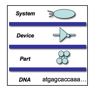
- Walk through one sample abstraction hierarchy that may guide synthetic biology
This abstraction hierarchy is modified from one of Drew Endy's slides. It gives us a framework for how to intentionally engineer various aspects of biological systems.


Part 1: Abstraction in action: Systems to Devices
first up: Arsenic detector

next: Bacterial buoy
Consider again the coliform project from the Melbourne 2007 iGEM team. The team listed six devices they needed to realize their idea:
- a red light sensor
- a blue light sensor
- an AND gate to trigger a cellular behavior when both lights are present
- a GFP reporter to monitor easily/quantifiably the AND gate's function
- expression of adhesive proteins under the control of the AND gate
- a gas vesicle expression cassette to produce naturally buoyant bacteria

After just 5 minutes we'll see the device level system diagrams that you've drawn for this system and discuss any outstanding questions or concerns.
and finally: Polkadorks
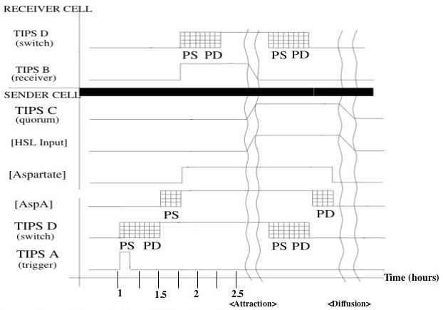
Let's try a more dynamic system. The 2004 IAP team wanted their engineered cells to "form, diffuse, and form again in random areas on the plate. Our system should thus form time-varying patterns based on local random time-varying symmetry breaking." Check out the Polkadorks animation.
- As a class we'll
- describe the system in plain language, then
- list the devices needed to implement the system
- Then as a team you'll have 10 minutes to draw a device-level system diagram.
- Finally, as a class, we'll look at the timing diagram that the 2004 IAP team wrote.

Part 2: Get busy!
Start applying these ideas to your team's project. You can work on a device list, a device-level system diagram and a timing diagram if you're ready. Be sure to keep your project notebook up to date and help keep each other great.
Week 7 Thursday
We've been working hard this week to move between the System and Device levels of an abstraction hierarchy and today we'll drop down one more level to think about the parts that make up a device. The device we'll consider is switch made from RNA, but first we'll look at a "classic" device, namely an inverter, and the parts that make it up.
Challenge: Abstraction in action: Devices to Parts
Part 1: Four-part inverter
Recall the Eau d'coli project from the 2006 MIT iGEM team. Their goal was to replace the nasty smell of bacteria with wintergreen smell during log phase growth and banana smell during stationary phase growth. In fact some of you added the banana smell generator (BSG) to bacterial cells yourself thanks to the Foo Camper's Guide to BioEngineering that we tried way back in Week 4 of this term. We also talked about the engineering ideas behind the Eau d'Coli project way WAY back in Week 1. Today we'll focus in on one device within the system, namely the inverter that was used upstream of the wintergreen generating device (WGD), turning it off during stationary phase.

Within this gene, we can define 4 "parts:" a promoter, a ribosome binding site (RBS), an open reading frame (ORF) that encodes the tet repressor protein, and a transcriptional terminator so the RNA polymerase transcribing the gene doesn't continue down to the next sequences downstream. The promoter is repressed by the tetR protein itself, allowing for a simple rearrangement that makes a useful inverter device. You can imagine a family of 4-part inverters that might be made for every repressor protein we know (lac repressor, lambda repressor, etc). The number of these proteins is finite, however, and there will almost certainly be a time when a transcription-based device will not be optimal, so for the next part of today's challenge you are asked to make an RNA-based switch. This challenge will draw upon your understanding of basic biology, your ability to find resources, and your ability to work as a team. Good luck!
Part 2: Toggle-away
Working in your project teams, develop a design for a genetically encoded toggle switch that can be flipped with exogenous inputs and that maintains one state (or the other) even in the absence of the input. Your team's design should include
- (a) a high level system diagram,
- (b) a full list of devices and parts,
- (c) timing diagram (time on the x-axis and devices on the y plus some indication of when their activities rise and fall, and
- (d) a plan for testing the most important components of your toggle.
You have 45 minutes.--so we've helped you get started by collecting some parts that you might find useful. These are parts that are documented, to different extents at the Registry of Standard Biological Parts.
Parts List (potential)
You can use parts that are not on this list. Try to find them in the Registry (where you could get them for free) or if you want to get them from another source, please specify and note associated cost, e.g. synthesis cost is $1/base, licensing agreements, etc.
Promoters
Reporters
- NOTE: This activity features an "All questions answered" work environment. Ask lots of questions.
- HINT: Spend 2 minutes right now thinking about all the things that need to come together over the next 45' for your team to be successful.
- QUESTION: How will you check that everybody on your team understands what is going on?
Why are we doing this??
After we hear from all the teams about their RNA-switch details, we'll consider what was challenging about this endeavor, what it revealed about building genetic programs, and how to optimize teamwork and productivity:
- from 2009: "it was hard...there wasn't enough time...we didn't know where to start...teamwork had to be figured out...being creative is hard...white boards helped...knowing a lot helps...to know things: ask others, research, copy existing ideas..."
