User:Peng Cao/Notebook/PHYC307L/oscilloscope: Difference between revisions
| Line 5: | Line 5: | ||
*[http://www-hep.phys.unm.edu/~gold/phys307L/manual.pdf PDF]. ([[Media:Gold's Junior Lab Manual.pdf|Here is a stored version of his PDF]]) | *[http://www-hep.phys.unm.edu/~gold/phys307L/manual.pdf PDF]. ([[Media:Gold's Junior Lab Manual.pdf|Here is a stored version of his PDF]]) | ||
*[[/Oscilloscope|Online]]. | *[[/Physics307L:Labs/Oscilloscope|Online]]. | ||
==Safety== | ==Safety== | ||
Revision as of 11:38, 15 September 2010
Introduction
The goal of this lab is to learn how to use an oscilloscope and practise for future labs.
More details and lab manual:
Safety
- Be aware of getting an electric shock.
- Turn power off before joint or disconnect cables and wires.
Preparation

- BK PRECISION 4017A(Function Generator)
- Tektronix TDS 1002(Oscilloscope)
- One BNC cable
- (why are they called BNC cables?)
- Should you use a T connector and a terminator?
Simply hook up the output of the function generator to the oscilloscope.
Procedures
Basic waveform measurement
At the beginning, I need to setup to get a sine wave on oscilloscope. After a few trails, I find out I can use "AUTO SET" button(On the top right corner of the oscilloscope). Then a sine wave appear.
Here are the measurements of the sine wave:
- Frequency: 111.8HZ (This changes all the time. After the measurement, it became 111.6HZ.)
- Period: 8.9?0ms (This also changes. Between 8.900~8.940ms)
- Amplitude:
- Use the grid: There are 4 intervals form 0V to the highest point. Each interval is 10V. Same as lowest. Just a little difference. So the amplitude is 42-(-43)=85V.
- Use the cursors: 40.8-(-41.6)=82.4V.
- Use the "measure" functions: 84.8V.
Then, I tried other frequencies. I find out when frequency is less than 100HZ, the oscilloscope can't work properly.
Here are my other trails:
 Frequency: 1.06?kHZ
 Period: 940.?us
 Amplitude: 84.8V
 Frequency: 11.?0kHZ
 Period: 91.??us
 Amplitude: 84.8V
 Frequency: 10.0?MHz
 Period: 100ns
 Amplitude: 89.6V
"?" means a uncertain number.
Triggering
Triggering can tell us what the votltage is on a certain period.
AC Coupling
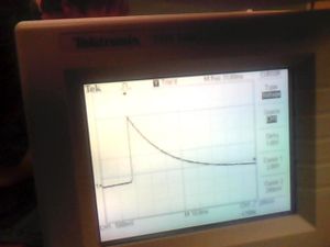
I used a lot of time to get a right graph on the oscilloscope. I need to turn off everything on the function generator and set the frequency less than 10Hz. And this time, the "Atuo Set" button is not helpful. It gave me DC settings. So I need to change it manually using "CH1 MEUN". Also, I need to use position and /DIV knob to get the graph. Here is my data:
 Frequency: 5HZ
 Amplitude: 4.6-(-4)=8.6V
 Fall time("measure" functions):86.58ms
Calculate Fall Time

- Cursor1: 2V (10% from top)
- Cursor2: 2mV (10% from bottom)
- Fall time: 52ms (about 5 intervals, each interval is 10ms)
Quesitions
- What RC constant does this imply? (See Wikipedia article on rise time)
- RC=t which is equal to fall time.
- How does this compare with the expected value for the oscilloscope? (Can you find the answer on Google?)
- We calculate fall time is using 10% of the peak voltage to 10% of the low voltage. The oscilloscope calculate from 10% of the rising edge to 10% of the falling edge, which is amplitude. So the fall times are different.
FFT
Use the math function, I can see a FFT graph. But I don't know what it is. After Steve Koch explan to me a little bit, I know it's about noisy.