Klapperich Lab: Fluid Cell Tip
From OpenWetWare
Jump to navigationJump to search
Overview
- The following manual describes the special steps needed when using a fluid cell tip for submerged testing
Materials
- 50 um Fluid Cell Tip
- Tweezers
- Superglue (if sample is not attached to AFM disk)
- Millipore Water (if using Fluid Cell Tip)
- PS-6 sheet from Vishay MicroMeasurements
Procedure
Start Up
- Reserve the TriboIndenter at Yahoo Calendars
- User Name: nanoindenter
- Password: hysitron
- Turn on the computer if not already on
Changing the Tip
- With the computer on and the TriboScan software closed, turn off the piezo and transducer controllers.
- Unplug the left cable from the transducer holder and the granite horizontal beam.
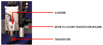
- Loosen the transducer holder by unscrewing the horizontal silver knob to the right of microscope.
- Slide the transducer holdlder upwards and out of the hood.
- Unscrew the tip using the tip tool and place in the hollow tube.
- Screw the tip in you desire stopping at the first sign of resistance.
- Slide the transducer holder back into place, connect the cables and retighten the screw.
- Turn both the peizo and transducer controllers back on.
- Rezero the tare value.
- Start TriboScan software.
- In the positioning window, go to Setup>>Tip Area Function. Select the correct tip area function.
Z-Axis Calibration in Air (Perform 1st and record in logbook)
- Change the microscope feedback gain to 100 on the TriboScope panel and in the software. From the Positioning window select Setup>>Piezo Controls and change the value for Front-panel Microscope Feedback Gain to 100. Minimize this window as a reminder to change the value back.
- From the positioning window, go to Setup>>Indent Open Loop Load Function.
- Set up the Load Function Editor to perform a 600uN 2-segment indent in air (AIR INDENT.ldf), for a total of 20 seconds. For soft materials, this load should be increased so that the air indent goes approximately 5um, but 600uN should be sufficient.
- From the Open Loop Load Function window, select Setup>>Advanced z-axis Calibration.
- Click "Calibrate Transducer." The instructions at this point from the pop-up windows are fairly self-explanatory.
- The calibration window will pop up. Check that the values in the table below are correct.
- Click done and follow the instructions.
- A graph will appear with a fitted functions of the Electrostatic Force constant as a function of displacement. Verify that that the fit is reasonable and close this graph.
- Make sure to write the ESF and ZVG values in the log book.
- Return the microsoft feedback gain to 1000 on the TriboScope and in the software by opening the window that was minimized earlier.
Parameter Correct Value Machine Compliance 4.0 Displacement Gain 100 Bias Offset 0.2001 Disp Micro Feedback auto detect Unchecked
Tip Optics Calibration
- From the positioning window, open the video window by clicking on the video button.
- Using the arrows in the Positioning window, move the optics to the PS-6 sample and find a "clean" spot to indent.
- You will probably need to disable the X-Y Safety Height. From the positioning window or the TriboScan Toolbar, select safety limits>>X-Y Safety Disable button.
- Change the video settings to white=30 and black=15 to increase contrast.
- Move up with the Z motor so that Z>15mm and tip will clear. Click on the create boundary button on the video window to create a sample boundary.
- From the positioning window, select Setup>>Indent Open Loop Load Function
- Open the load function, AIR INDENT.ldf.
- Zero the tare value.
- From the Positioning window, select Setup>>Calibrate Optics>>Stage Offset>>New Single Indent.
- The software will prompt you to adjust the tip height to about 1mm from the samples surface using the green arrows. Click OK after you have done this.
- After the indent move down in Z to be in focus on the sample. Do not move in X or Y.
Z-Axis Calibration in Water (Perform before indenting on sample)
- Change the microscope feedback gain to 100 on the TriboScope panel and in the software. From the Positioning window select Setup>>Piezo Controls and change the value for Front-panel Microscope Feedback Gain to 100. Minimize this window as a reminder to change the value back.
- From the positioning window, go to Setup>>Indent Open Loop Load Function.
- Set up the Load Function Editor to perform a 600uN 2-segment indent in air (AIR INDENT.ldf), for a total of 20 seconds. For soft materials, this load should be increased so that the air indent goes approximately 5um, but 600uN should be sufficient.
- Move indenter tip into the water more than 5 microns above the sample.
- From the Open Loop Load Function window, select Setup>>Advanced z-axis Calibration.
- Click "Calibrate Transducer." The instructions at this point from the pop-up windows are fairly self-explanatory.
- The calibration window will pop up. Check that the values in the table below are correct.
- Click done and follow the instructions.
- A graph will appear with a fitted functions of the Electrostatic Force constant as a function of displacement. Verify that that the fit is reasonable and close this graph.
- Make sure to write the ESF and ZVG values in the log book.
- Return the microsoft feedback gain to 1000 on the TriboScope and in the software by opening the window that was minimized earlier.
Parameter Correct Value Machine Compliance 4.0 Displacement Gain 100 Bias Offset 0.2001 Disp Micro Feedback auto detect Unchecked
Performing A Displacement Control Air Indent
- From the positioning window, go to Setup>>Indent Displacement Control Load Function.
- Open load function, "4000nm_AirIndent".
- Move tip to be in contact with the sample by watching the tare value
Notes
It is sufficient to calibrate tip area function once a every few months and/or with a new tip
Contact
- Jessica Kaufman
- Eben Tessari
